Had to share this nice digital Orrery...
http://dd.dynamicdiagrams.com/wp-content/uploads/2011/01/orrery_2006.swf
Tuesday, February 8, 2011
Saturday, February 5, 2011
Cutting wood!

So as you can see I've started cutting the gears.
Whew! When I said this project would be a 'zen' project, I was not kidding! Each large gear wheel takes approximately one and a half hours each, obviously less for the smaller gear wheels.
I've been having small issues knowing what printing settings to use when printing off the paper templates. What I do is print the gears on paper at a scale of 1 to 1, then spray adhesive on the back and stick to the thin ply that I've decided to use. If I don't pay attention to the printer settings, errors will occur. And considering the tiny tolerances of the teeth, all the gears MUST be printed with the same printing settings. One bit of good news is that Alibre (my CAD program) and Inkscape (I used this to generate the gear designs) both print accurately. So when I print the gears with the CAD changes and compare them to the Inkscape print jobs, they match. That is GOOD NEWS.
Then off to the scroll saw. I should be using a band saw, but I'm thinking it that might be too aggressive, and not as delicate for the smallish teeth. I was going to use thicker Russian Birch ply, which is very nice but expensive stuff, but realized that was over kill, at least for the gears. If I use a fine scroll saw blade, and take my time, the gears come out fine. I'm using three separate layers of ply for each large gear. I wanted to add a design detail and cut down on the weight a bit. You can see the layered effect I am after in the photo above.
Other news concerns the bearings for the arbors. I've sourced out a company in the U.S. called Igus that make all plastic bearings. ( http://www.igus.de/default.asp?PAGE=IGLIDE) After chatting with a sales rep, I've got free samples of the various sizes I'd like to use in the mail. I asked for pairs of each so that I might make a jig and test how well they cut down on the friction. I should get those soon I hope! If they work well I may buy fifty or so at a time for future projects. (A clock?)

And finally cryptic a view of my completed gearbox.
It's not there 100 % yet, but the dimensions are fixed. The only modification I need to make is with the placing of the plastic bearings mentioned above. More on that when I receive my free samples. Tee hee hee!
Time to put on the dust mask again and get busy!
Monday, January 24, 2011

Next hurdle: designing a self-contained 'gear-box' so as to ease the construction of the whole piece. I want to be able to remove all of the gear assemblies in one package instead of relying on the structure of the table to support the gears. This will make things much easier in the long run...
Sunday, January 23, 2011
 Well it's coming together pretty quickly. Today was all about refining the design of the gears and how they nestled inside each other. I'm confident enough now to start the work on the table design. Picked up a nice fat antique bible for 20$ with lots of purdy pictures which I will carefully go through to choose a for design ideas. It's looking like some of the design details from (of all things) grandfather clocks are catching my eye. I've also chatted up my pal Russ for some advice for ageing and staining the piece to make it look nice and old. Should have the digital version finished up in a couple days...
Thursday, January 20, 2011
Mars Orrery, first baby steps

You can tell I'm excited because here's a second post in just a few days...Which is saying a lot as I'm trying to figure out a career change and heavy life stuff at the same time. This little project will be my 'Zen' path as I struggle through that...
So I've started the visualization of the piece using Alibre. That's a pretty smart way to go because I need to space the drive and idler gears properly. They transfer the power from the yet to be made crank to the main wheels for each Martian objects in equal time. As described before, as Mars makes one full rotation, the moons should move at their own speed. Using lots of same sized gears, idler gears, and even numbered ones so as not to change the direction, hopefully will accomplish this. It might not be the most efficient design, but it'll get 'er done! I'm hoping to optimize the space needed and fit everything into a small open-framed box that can be slid into a nice antique-looking display table.
Next step, careful design of the main wheels so that they nest one inside the next. If you look at your average clock, the second, minute and hour arbors nest very delicately within one another, with the hands carefully attached to the top of each 'tube' or arbor. I have to accomplish the same thing but on a larger scale.
More soon.
Tuesday, January 18, 2011
It's been a while, but now a new project --- MARS.
 |
| a quick sketch of my Mars Orrery |
The Karakuri plans are still very slowly chugging along, but I've been derailed as it were by a lack of spring steel that's an appropriate size. Until I have a source for this there really is no point in starting the construction, so for now I've begun to develop plans for a long overdue project. It's still good practice for the Karakuri, so for now I'm content with just making something complicated.
For the last ten years or so I've been floating the idea around of making an Orrery ( http://en.wikipedia.org/wiki/Orrery ) of Mars and it's two moons Deimos and Phobos. Made completely out of wood one would turn a crank, Mars would turn on it's axis, and the two moons would rotate at the appropriate orbital speeds. I'd design it to look old and use on Schiaparelli Mars maps, canals and all, as the design basis.
To make this work would require knowledge of Mars and it's moons (Check! - says the space geek), how to construct wooden gears (check!) and the hardest part, understanding and designing a gear train. Wait a minute, that's pretty hard. Well with much hair pulling I have figured this out, and made a mock-up to test it out.
 |
| the start of the process... what a mess |
To the right here you can see I've started drawing out the concept. I figured out the wheel size and teeth numbers based on the orbital period of the two moons. I assumed that if Mars rotates one complete rotation on it's axis, one day, then the orbital periods of the two moons should be rough percentages of 360 degrees, one full rotation.
 |
| model made! |
So here I have made a mock up of the Mars system and what I hope are the correct sizes of the wheels for this orrery. I carved them out of foam-core, and glued rubber bands to the edges with double sided tape. Carefully aligning and using toothpicks for pivots, I'm ready to test out my maths.
It turns out that for every rotation on Mars, Phobos takes 1.26 times the rotation of Mars, while Deimos takes .32 times the rotation of Mars. Basically Phobos orbits very quickly, crossing the Martian sky in lest than a day, while Deimos just creeps along, actually looking like it moves across the sky in the opposite direction!
So here's the plan; I carefully turn the driver gear in the center (that could be any size, I designed this one smaller, you'll see why in future posts) allowing Mars to turn one full revolution, or one full day. I mark the start positions of the wheels. I carefully count how many times the Deimos wheel turns, which should be more than once because it's smaller than the Mars wheel. Then how many degrees the Phobos wheel turns; this should be less because the wheel is larger than the Mars wheel.
Results!
 |
| the results, not bad considering the slippage of the elastics! |
I counted the Mars full rotation as 360 degrees. I then counted the Deimos rotation as roughly 2 3/4 rotations, or 990 degrees. Phobos as roughly 280 degrees. Divide 360 into 990, you get .363. The actual orbital period of Deimos is .319. Pretty close!
Divide 360 into 280, you get 1.29. The actual orbital period of Phobos is 1.26! Almost spot on!
So with this gear train designed and tested, allowing for a little bit of error, I am ready to start cutting wood. Well sort-of. Due to the fiddly-ness of the meshing of the gears, I will have to make a detailed 3D plan, as like the Karakuri doll, to make this work well.
I'm so please I'm ready to make this I'm giddy, it's been ten years in the making.
Stay tuned!
Tuesday, October 5, 2010
distracted by another project...
Hello again,
Just a quickie.
Well no posts for a while, that's because I've been asked to design a new matte cutting table for my wife Aud. She has a custom picture framing shop in Vancouver, and is in desperate need of a new table. It's sort of related to my Kurakuri as I've used the new CAD software to design it, and in the process learned quite a few more tricks. Here's a still-
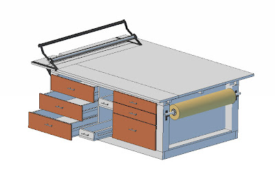
More soon me hopes!
Subscribe to:
Posts (Atom)