Check this link out regarding Creepy automata displayed in churches in the 15th century
There's a link on this page to a Standford University publication that goes into quite a lot of depth about these 'Satan' automata used by the church to scare people into attending regularly. Happy Easter!
Sunday, April 24, 2011
Changes, and lots of fiddlin'
In the last day and a bit I've found a little time to work on the smaller gears in my Mars Orery. I'm a little apprehensive because this is where I will see where all the small errors will add up to a gear train that doesn't want to move. I expected this, so now the task of sanding the teeth down and finely adjusting the spaces between the gears comes into play...
The first task was to assemble the pinions of the smaller idler gears. I made a jig for my Dremel so that I could round off the tips of the dowel, but found the standard hardware store dowel was far too soft, and so the rounding bit tore the hell out of the ends of the stock. I alleviated this by buying some 1/2 inch oak dowel.
After the rounding off was done it was time to drill the 1/4 inch hole for the pinion dowel. The 1/4 inch dowel fit a bit too tightly into the new Igus plastic bearings, so some careful sanding was needed. If you ever try to make something similar, word of advice, source out accurate dowel. That has been the biggest money waster so far, badly made dowel. Take some calipers with you on your shopping trips if you don't want to be disappointed!
I next took quite a while making sure the 'arbor supports', the small planks that hold the gears apart, were spaced properly and the counter-sunk holes for the bearings were perfectly measures and drilled. This took the better part of an afternoon and a few gimmicks to make this work.
By the end of the day I had the gearbox roughly together, and just like I suspected, not much would move. There's many hours of fine tuning ahead. AND the actual driver gears and mechanism still has to be made. I've fiddled with making some beveled gears, but at this point I suspect a simple wheel/dowel type of gear might be the best approach. We'll have to see...
So the current state of the gearbox is encouraging but daunting at the same time. In the image here you can see the top of the gearbox looks pretty complicated, but not for long. The circular bearings I made would not work due to the minor errors in the whole design, so I opted to make small UHMW plastic bearings to do the job, and they seem to be working well. The top outer plate there will look simpler and should be an even flat surface before too long.
Onto teeth sanding using a large cut-off wheel that I've stuck sandpaper to. Better wear a mask for that!
The first task was to assemble the pinions of the smaller idler gears. I made a jig for my Dremel so that I could round off the tips of the dowel, but found the standard hardware store dowel was far too soft, and so the rounding bit tore the hell out of the ends of the stock. I alleviated this by buying some 1/2 inch oak dowel.
![]() |
my cute little collection of idlers |
After the rounding off was done it was time to drill the 1/4 inch hole for the pinion dowel. The 1/4 inch dowel fit a bit too tightly into the new Igus plastic bearings, so some careful sanding was needed. If you ever try to make something similar, word of advice, source out accurate dowel. That has been the biggest money waster so far, badly made dowel. Take some calipers with you on your shopping trips if you don't want to be disappointed!
I next took quite a while making sure the 'arbor supports', the small planks that hold the gears apart, were spaced properly and the counter-sunk holes for the bearings were perfectly measures and drilled. This took the better part of an afternoon and a few gimmicks to make this work.
![]() |
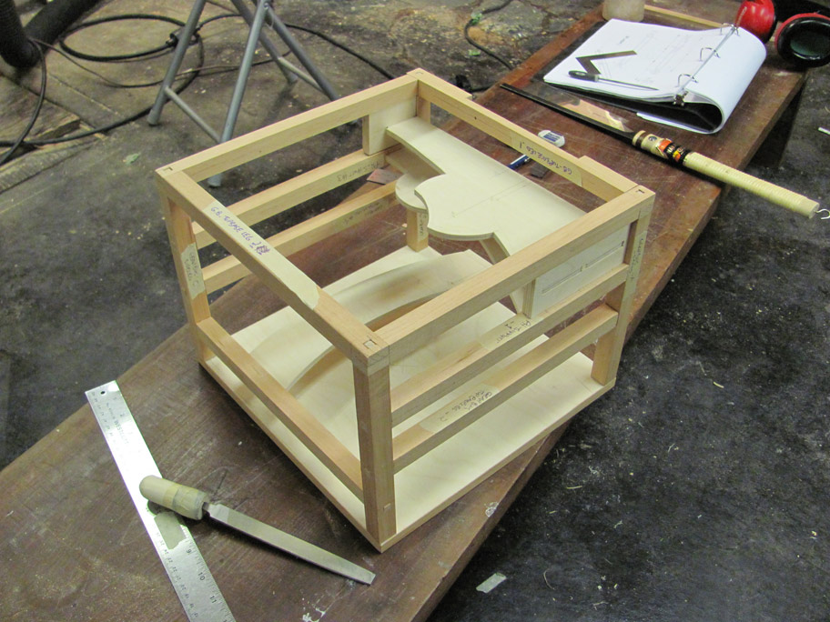
the first dry fit - very little movement but it did fit together! |

Onto teeth sanding using a large cut-off wheel that I've stuck sandpaper to. Better wear a mask for that!
Thursday, April 7, 2011
The 'Orbital Plate Bearings' take shape...
One feature in my little gearbox that I've failed to talk about are what I'm calling the vital 'Orbital Plates' and the associated top portion of the gear box. These are actually very important parts of the design as these will keep the three separate geared plates in alignment and vertical.
The Deimos, Phobos and Mars gears are attached vertically with cages of dowel to various sized plates. (Well actually the Mars gear is strictly a 1/2 inch dowel up the very center...) These plates have about 1/8 of an inch clearance from one another and the outside recess of the top of the gearbox. Have a look at these photos and you'll see what I've decided to do.
I've made my own coasters or wheels about an inch across out of Alumilite casting resin to surround the two plates. I was hoping to find one inch nylon coasters but the local hardware store were kinda low on those. We'll see how they ware, but in my experience the Alumilite is pretty tough..
For the vertical friction I've cut out and shaped 1/8 thicknesses of UHMW from Lee Valley. If you're unfarmilliar with this stuff, UHMW stands for Ultra High Molecular Weight and is perfect for frictionless bearings. It's a bit tough to cut, but not impossible. A good sharp xacto blade helps, but use some of that green High-Friction Guard Tape on yer fingertips if you want to keep them. I plan to next rout out 1/16th deep grooves for the UHMW to sit in and I'll attach with very small brass screws.
As for the rest, well it's looking like this:
Next : making the gear assemblies. The bearings hopefully arrive tomorrow!
Sunday, April 3, 2011
latest on the Antikythera Device
Check out the latest on the Antikythera Device, an ancient Greek clockwork calendar...
It's amazing what they accomplished a thousand years before clockwork mechanism became the norm...
(link via Wired)
Monday, March 28, 2011
Amazing kinetic sculptor from San Fransisco
Check out this amazing kinetic sculptor by the name of Reuben Margolin from San Francisco.
I can only dream of this sort of complexity for now. Wow!
(Goto the YouTube site and watch in HD, it's stunning work!)
Sunday, March 27, 2011
The Gearbox takes shape...
Steady progress has been made constructing the gearbox that will hold all the wooden gears and bearings. Despite having measured drawings and cutting carefully, I made a few minor mistakes getting the dimensions just right. No amount of detail and careful execution helps when cutting wood is involved. It swells and warps depending on humidity, and if you pencil lines are just a smidge one side or the other, these can all add up to a couple millimeters of error.
The first attempt at fitting parts together had a few issues. Some of the cross braces were a few millimeters out and made any attempt to fit this complex box together quite difficult. Word of advice, when making wooded parts for something like this, a mm or two of give may be a good idea. Also triple check your drawings. Some precise alignments might make sense if this were metal, but you need give when working with wood.
Though as you can see here after a bit of filing and nibbling with my saw it fit together nice and tight.
There is no glue used here, but it holds together just fine. I'm using straight grained fir and various thicknesses of Baltic birch ply. I eventually plan to stain darker and polish with various waxes to give it an 'antique' look...
Next: finish a couple more gear support parts, then on to installation of the bearings and gears (taking into account the slight measurement changes), and designing a new driver gear.
Thursday, March 17, 2011
quick update
Well poor Japan has been hit once again with tragedy. It's hard not to look at the news images after visiting such an amazing country. Many places I personally visited and enjoyed the most were small coastal towns and cities, much like Sendai and Fukushima. It's so heartbreaking to imagine all those lives just gone and swept away by the sea.
I'm trying to distract myself with new career plans and of course working on the Mars orery when I can.
Here's the latest image of my CAD edits as I plan the gearbox out...
The small red things on the end of the blue idler wheels are 3D representations of my new Ignus plastic bearings that I have received as samples. ( http://www.igus.com/default.asp?PAGE=IGLIDE) What's great here is that this is all to scale, so I've gone ahead and made quite a few of the smaller parts. What is not shown here is that I've replaced the four smaller idler gears with two larger ones. So long as all the gears are in pairs (as with the other two trains) and not singles, the direction of movement will still remain the same.
I've recently made a jig so that I can round off the ends of the 1/2 inch pinions with a router that has a round-off bit with a 1/4 inch bearing. It took a few tries but it seems to be working well.
Next is the supporting frame.
More soon...
I'm trying to distract myself with new career plans and of course working on the Mars orery when I can.
Here's the latest image of my CAD edits as I plan the gearbox out...
I've recently made a jig so that I can round off the ends of the 1/2 inch pinions with a router that has a round-off bit with a 1/4 inch bearing. It took a few tries but it seems to be working well.
Next is the supporting frame.
More soon...
Subscribe to:
Posts (Atom)